CASE STUDY
Waste Heat Recovery | Product Stream Heating
| PLANT LOCATION | Middle East |
| FACILITY DESCRIPTION | Refinery |
| BOILER TYPE | Forced Circulation |
| BOILER CAPACITY | 3 [MW] |
| STEAM CONDITIONS | Product heated to 160 [°C] |
Conditions:
A refinery identified an opportunity to improve operating efficiency and reduce internal energy consumption by preheating a product stream and extracting heat from the tail end of a cat cracker exhaust stream.
Design Boiler [DB] designed a complete heat recovery system that required minimal draught plant modifications and maintain low fan power requirements. Following a comprehensive thermal design analysis, a full set of certified fabrication drawings were prepared for use by a third party contractor for manufacture.
A two stage finned tube heat recovery unit was designed to achieve the client’s heat recovery specification. One of the challenges involved in the design of the ducting system was the requirement for it to be installed into the existing self-supported stack within the available time-frame of the annual plant shut down.
The final optimized design included wide gas flow areas across the main heat recovery unit and a number of tight upstream duct bends with irregular inlet and outlet profiles. Such features can potentially cause an uneven gas flow across the heating surfaces which can detrimentally affect heat recovery performance and increase draught losses. Upstream low straightening strategies including perforated plates across the face of the heat recovery unit and turning vanes on bends were designed and incorporated into the ductwork.
The plant was installed and commissioned over the annual shut down period with minimum interruption to the operation of the refinery. It achieved its intended payback within the anticipated period and has continued to provide many years of trouble-free service.

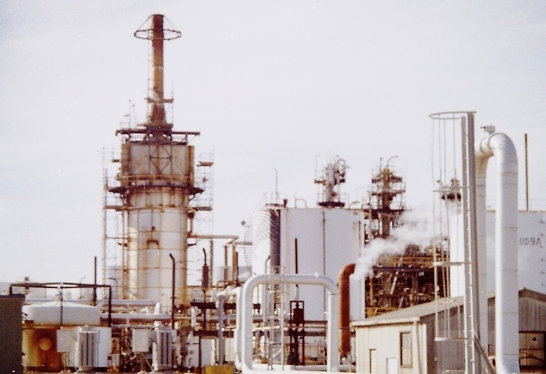
A typical petrochemical processing refinery. There are many opportunities to recover waste heat in these plants.
